11kv high voltage ht metering connection with ct & pt Switch test abb point power ct mega poles connected pt rear How to wire ammeter with current transformer (ct coil)
Current Transformer Installation For Three Phase Power Supply- CT Coil
Ct and pt connection diagram explained 6 electrical tests for current transformers explained Current transformer connection to meter diagram
Current diagram transformer wiring ratio ct polarity test direction transformers primary electrical secondary explained instantaneous multi tests assumed correct under
Ct cores secondary circuit connection diagramCt test block wiring diagram Transformer transformers metering polarity electrical equivalent explained delivering producers consumers interconnected electricity injecting17 fresh ct test switch wiring diagram.
Burden transformers cts talema windingTransformers polarity transformer connection markings relay ratio wire explained occasionally misapplied verify 9v multimeter Test wiring shorting switches relay typicalTransformer current ct principle working connected construction line coil secondary series electrical turns ammeter wire operating made.
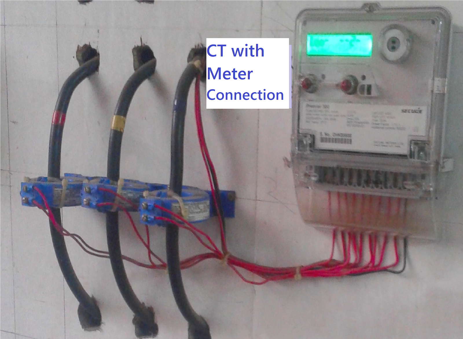
Current transformer installation for three phase power supply- ct coil
Current transformer test blockWazipoint engineering science & technology: current transformers –ct using Ct and pt connection diagram explainedCt shorting block wiring diagram pdf download ~ 424 download epub.
Introduction to current transformers (cts) : the talema groupCt meter How to connect ct & pt to switchgear connection diagramSingle phase ct wiring diagrams.

Ct current series transformers two metering relays protection cts meters wired electrical classes combined
Video: how to properly short a ct shorting block?Current transformer (ct) Current wiring ammeter digital ct transformer diagram circuit coil meter switch electrical electric ampere board power generator panel energy connectionsAbb / ite / bbc mega power 10 point uts1 test switch.
Transformer yj prostartCurrent transformer wiring installation ct diagram phase coil power three supply meter connect electrical coils amp so Ct wiring diagramThree phase 3 phase ct meter wiring diagram.

Wiring diagram ct metering
Current transformers (ct's) wired in series for two meters or relaysDigital ammeter wiring with current transformer Relay test switchesTest ft switch typical plugs switches ppt powerpoint presentation connection pole.
6 electrical tests for current transformers explainedAmp meter current transformer wiring diagram Ct connect switchgearCt shorting block wiring diagram.
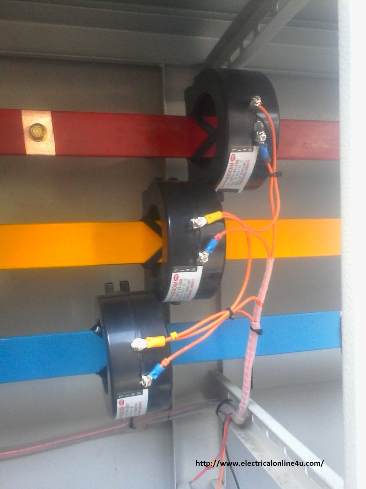
3 phase ct connection diagram
Current transformer wiring diagramAmmeter current transformer coil Current transformer wiring diagram phase ct meter coil three installation wire ammeter power ampere connection electrical supply transformers meters voltDigital ammeter wiring with current transformer.
3 phase ct meter wiring diagramsTransformer metering circuit connected secondary rated ratio Ammeter wiring transformer current digital ct diagram coil transformers wire electrical connections articleCurrent transformer installation for three phase power supply- ct coil.

Ammeter connection diagram with selector switch and ct
.
.


Amp Meter Current Transformer Wiring Diagram
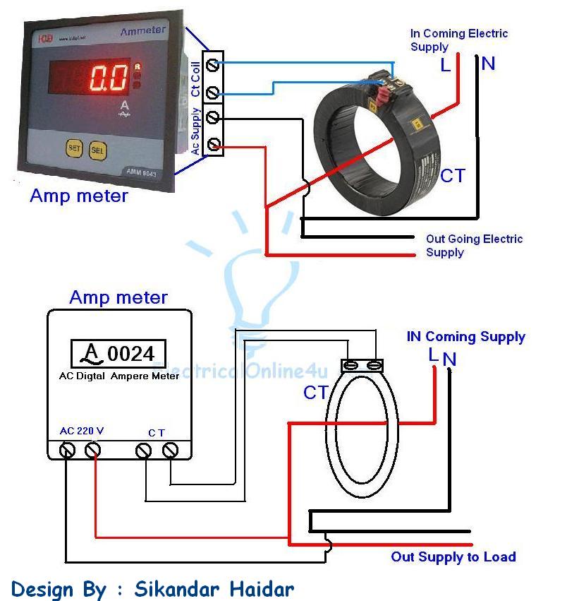
Digital Ammeter Wiring With Current Transformer - CT Coil | Electrical
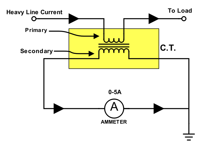
Current Transformer (CT) - Construction and Working Principle

Three Phase 3 Phase Ct Meter Wiring Diagram - Organicica

Current Transformer Connection To Meter Diagram

CT and PT Connection Diagram Explained - ETechnoG
